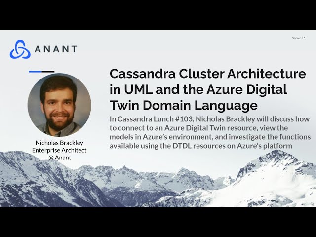
In Cassandra Lunch #103, we discuss the UML Architecture of a Cassandra Cluster and discuss the Azure Ecosystem’s new tool the Digital Twin Explorer. You can download the files used in the Digital Twin Domain Explorer demo on our Github.
UML, the Unified Modeling Language, is one of the primary languages used in the process of architecture definition. It can be used to define the logical, functional, and physical components and structure of a system.
Three Types of Architecture
Industry best practices for architecture typically split architecture into three types.
Functional Architecture
Functional architecture defines relationships between concepts in an enterprise. A well-managed functional architecture will define the system’s logical behavior, but won’t define the physical locations responsible for hosting the classes and services defined in the functional diagram.
Functional architecture includes UML Class, Sequence, and State Diagrams.
One outcome of a functional architecture is the definition of the databases and data architecture that need to be managed for your system.
Generic Physical Architecture
Generic physical architecture defines the locations and groupings of the services and places them on physical devices. It doesn’t select specific service providers for each service.
UML diagrams associated with generic physical architecture include Component, Package, and Deployment Diagrams.
One outcome of a generic physical architecture is a deployment agnostic architecture that can be instantiated on any cloud provider.
Specific Physical Architecture
Specific physical architecture specifies the nodes and services defined the the generic physical architecture.
The UML Diagrams associated with specific physical architecture are Deployment and Node diagrams.
The outcome of a specific physical architecture is a system definition with service definition selections that can be used to generate sprint plans and fully realized feature backlogs.
Three Main Relationship in a Class Diagram
There are three relationships that define the most important connections between elements in the UML Class Diagram. These relationships clarify the parts of the diagram.
| Relationship Name | Explanation | Translation From English | Arrow Shape |
| Association | the most generic relationship in a Class diagram connecting two classes | “has a” | solid black triangle |
| Composition | a relationship indicating that on class is a component of another class | “composes” / “is composed of” | solid black diamond |
| Inheritance | a relationship indicating the one class is a subclass of another – implying that the sub-class can inherit the properties and operation of the class | “is a” | open white triangle |
Functional Architecture Diagram for Cassandra Cluster Architecture: Class Diagram

Some of the relationships defined in this class diagram include;
- A Cluster is composed of Data Centers
- A Data Center is Composed of Racks
- A Node has software and Data
- A Data Center is a Physical Building
Generic Physical Architecture Diagrams for Cassandra Cluster Architecture
Below is an example of a node diagram that crosses the boundary between generic and specific physical. Node diagrams specify structure in the system – the rectangular boxes are physical or logical machines or groups of machines. Because Airflow, Cassandra, and Kubernetes are specified, this diagram crosses into specific. The most important information communicated by node diagrams like this one is the location of specific services within containers.

Specific Physical Architecture of a Cassandra Cluster
The diagram below is one example of a Cassandra cluster. Notice that the cluster shown below has specific services such as Kafka, Spark, Cassandra, and Akka selected. A more thorough specific physical architecture would include more information about how the nodes are connected, including information about ports and service connections.

Digital Twins, What and Why?
A digital twin is a simulated system. Ultimately, a digital twin can be simple or complex; however, to be effective, it needs to capture information both about your system and environment that surrounds it. The system is embedded in the environment and can be used to estimate measures of effectiveness and performance.
Digital twins place the system defined by architecture into scenarios specified by the creator of the digital twin. This is vastly more flexible than a series of stress tests, as scenario definitions can provide insight into the performance of the system over time and in unusual siuations.
The most mature form of a digital twin will pull values from sensors in the real world. You can then use Azure’s models, CLI, and queries to observe and manage the system. You can also add scenarios to project system performance over the entire life-cycle of a system.
Azure Digital Twin Explorer Demo
1.0 – Access your account on the Azure Ecosystem
You’ll need to register and certify your identity on the Azure Ecosystem. How to do this is beyond the scope of this
1.1 – Create a Resource Group

1.2 – Create an Azure Digital Twin Resource Instance

Note that you can accomplish steps 1 and 2 in a single step through the specified “Create New” option.

Fill out the required fields. Notice that you can either create a new resource group or identify the one you created in step 1.1.
Be sure to check the “Assign Azure Digital Twin Data Owner Role” box.
1.3 – Open the Azure Digital Twins Explorer

1.4 – Upload your files to Generate the Model

You can upload an entire folder of models using the option in the red box or a single file using the option one to the left of the box.
Once you have added files to the model. You’ll see that the classes appear in the model, without specific relationships. That’s because the relationship aren’t explicitly defined is this demo until the scenario is uploaded in step 1.5.
1.5 – Upload the Scenario to instantiate it by giving values to the properties you’ve defined.

The red box indicates where you can upload the scenario.
Once you’ve uploaded the scenario you will see the specific relationships in the model view.

Resources
Basic Information about DTDL – https://docs.microsoft.com/en-us/azure/digital-twins/concepts-models
Query Language Reference – https://docs.microsoft.com/en-us/azure/digital-twins/reference-query-clause-select
Digital Twin CLI – https://docs.microsoft.com/en-us/cli/azure/dt?view=azure-cli-latest
Floor and Room Demo – https://docs.microsoft.com/en-us/azure/digital-twins/quickstart-azure-digital-twins-explorer
Cassandra.Link
Cassandra.Link is a knowledge base that we created for all things Apache Cassandra. Our goal with Cassandra.Link was to not only fill the gap of Planet Cassandra but to bring the Cassandra community together. Feel free to reach out if you wish to collaborate with us on this project in any capacity.
We are a technology company that specializes in building business platforms. If you have any questions about the tools discussed in this post or about any of our services, feel free to send us an email!


